
Installation & Instructions
for Saltwater Chlorine Generator System
Pool Spa Efficiency LLC Manual Version: 01/01/20 Made in the USA
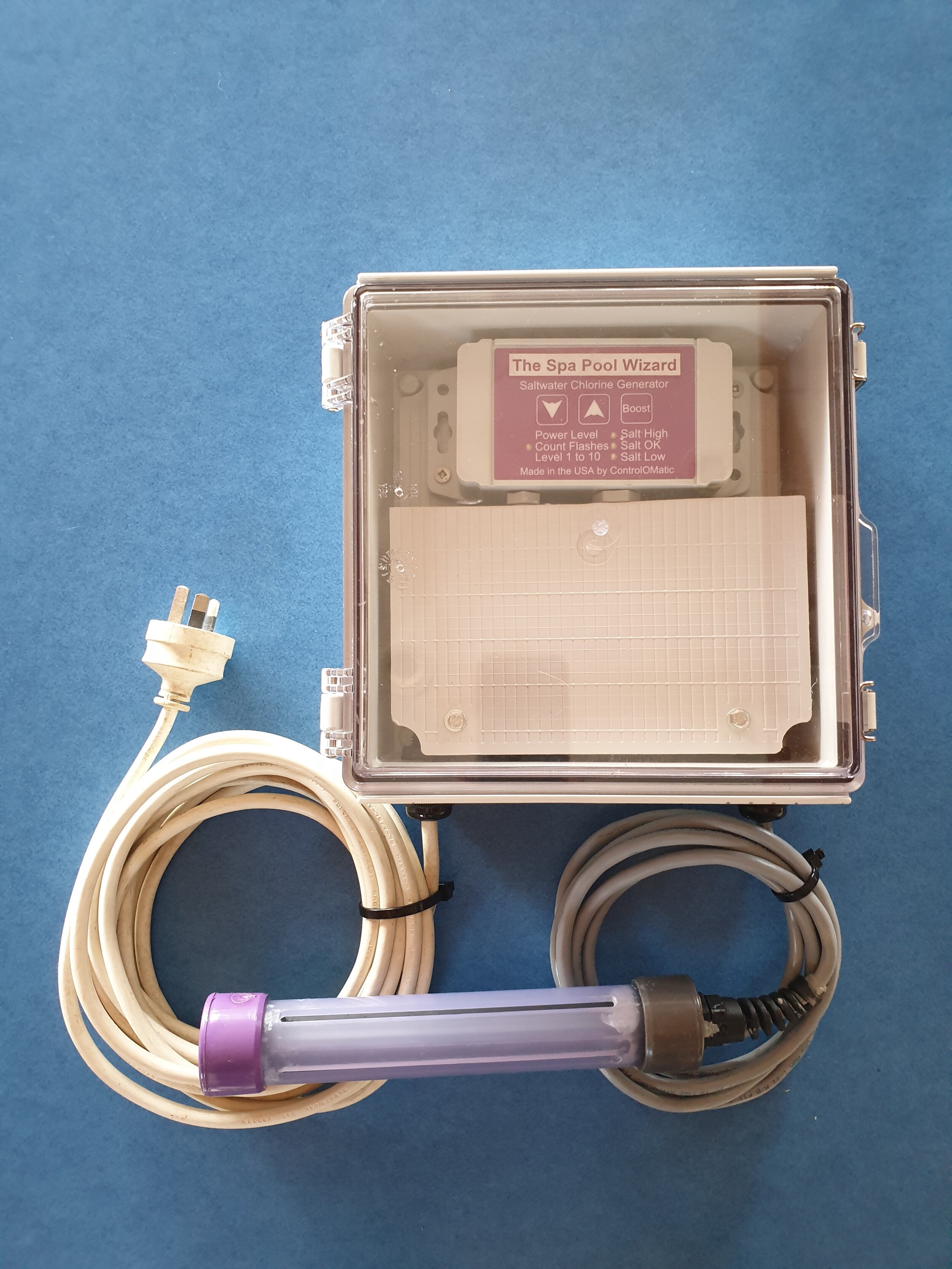
Complete 230VAC System mounted in optional IP66 Enclosure. Power supply and Controller mounted in weather-proof and dust-proof enclosure, with input 230VAC cable and Cell connection cables through water-proof glands.
IMPORTANT SAFETY INSTRUCTIONS
When installing and using this electrical equipment, basic safety precautions should always be followed, including the following:
WARNING: Cutting the cord from the power supply to the cell voids the warranty. Damage will occur if the power connection polarity is reversed.
WARNING: To reduce the risk of injury, do not permit children to use this product unless they are closely supervised at all times.
WARNING: Use only according to these instructions. Any modification or misuse of this product will void the warranty.
WARNING: Install in accordance with all national and local electrical, plumbing, safety, and other applicable codes.
WARNING: Connect to a GFCI (ground fault circuit interrupt) or GFI (ground fault interrupt) protected VAC power source only. (RCD – Ensure that as minimum a Residual Current Device is in place in the circuit delivering the VAC power to the Controller).
WARNING: Protect the power supply and outlet from exposure to the elements including direct sun, rain, snow, condensation, etc.
WARNING: DO NOT use with extension cord. Injury may result.
WARNING: DO NOT operate if damaged in any way.
WARNING: DO NOT pull on the cord to disconnect the Power Supply from power source.
WARNING: DO NOT operate or leave the power supply in temperatures below -10ºF or 0ºC.
WARNING: Disconnect, remove and store indoors when spa has been winterized or drained.
CAUTION: Leave spa cover open at least 1 minute to allow trapped gases to escape prior to use.
CAUTION: Measure water quality parameters and adjust if necessary prior to each spa use.
CAUTION: The system must be adjusted properly in order to not over-chlorinate your spa. Over-chlorination can lead to spa damage and un-healthy water conditions.
WARNING: Remove the cell from the SPA when using the SPA.
WARNING: DO NOT handle the cell during chlorine production (visible bubbling). Slight discomfort may be felt in cuts, sores, or sensitive skin areas due to chlorine concentration and the electrolysis process.
WARNING: DO NOT insert objects into, or tamper with the cell in any way. Inserting metal objects into the cell may cause damage and void the warranty.
WARNING: DO NOT plug control box directly into the VAC supply, this will cause damage. Always use the low voltage power supply.
CAUTION: While the Controller Unit is contained in a water resistant package, we strongly recommend that the unit be located away from direct sunlight and rain. Consider mounting the Controller Unit inside a water-proof enclosure.
INTRODUCTION
The Spa Pool Wizard Chlorine Generator System is the result of many years experience with ORP control systems and salt systems. Data collected from ORP controllers found operating on a 3 hour cycle to be ideal. The chlorine in a spa will dissipate quickly due to the warmer temperatures of the water, so the system operates with a short 3 hour cycle time to ensure sanitizer levels are maintained. After the salt is converted to chlorine, the chlorine will later be converted back to salt, keeping the salt level steady. Small amounts of salt will be lost when bathers leave the spa.
WATER PREPARATION & MAINTENANCE
To ensure proper operation, the spa must be drained, rinsed, refilled with fresh water, and balanced to the recommended levels indicated in this section before installing the product. Use the included test strips to measure water chemistry and verify the water is properly balanced. Replacing the filter is recommended, but not required unless, the spa was previously sanitized with a hydrogen peroxide system. The combination of hydrogen peroxide and chlorine may cause gum-like build up, water discoloration, and skin irritation.
It is important to properly maintain your spa for the health and safety of all users. Spas are unique in both size and usage patterns. The Hot Tub Wizard will significantly reduce the amount of spa maintenance required, but regular chemical checkups, including chlorine levels and pH, are recommended. Proper water maintenance will prolong the life of system and the spa. The following table describes generally accepted optimum water chemistry for portable spas.
It is recommended that chlorine and PH levels are Parameter Recommended Level checked before each use, or at least once per week when not in use. Alkalinity, Calcium Hardness, and Free Chlorine 2.0 to 3.0 Salt Concentration should be checked at least once a month. pH 7.2 to 7.6. It is recommended that the spa is manually shocked after high usage (example: after a party with multiple users), or biweekly if used frequently. Total Alkalinity be kept at 80 to 120 PPM. Calcium Hardness 250 to 400 PPM circulating for several hours before retesting.
Phosphates in the spa water will increase the demand for chlorine and will reduce the life expectancy of the generator. Remove Phosphates upon start up and each month thereafter. Phosphate Remover can be purchased at any local Pool & Spa supply store.
WARNING: Consistent chlorine levels above 5.0 PPM (parts per million) or consistent salt concentration levels above 2,500 PPM may lead to corrosion of metal components in the spa.
WARNING: Consistently low Calcium Hardness levels below 250 PPM may lead to spa equipment damage and failure. Make sure Calcium Hardness levels are within the recommended range above. This will also eliminate the need for the installation of a sacrificial anode.
SALT REQUIREMENT
The Spa Pool Wizard system will generate chlorine using non-iodized Sodium Chloride Salt. SALT ONLY NEEDS TO BE ADDED ONCE AND BROUGHT TO THE APPROPRIATE SALT LEVEL (BLUE LIGHTS) PER SPA WATER CHANGE. USE CHLORINE SALT - SODIUM CHLORIDE (NaCl): Raise Salt Level to 1,500 to 2,000 PPM (Parts Per Million).
Approved salts include “pool salt” made for salt water chlorine generating systems, canning and pickling salt from your local market, and some water softener salts that are 98-99% pure sodium chloride or better. Some high-end, mineral enriched salts can be used but require higher quantities to achieve 2,000 PPM sodium chloride salt level. These approved salts are generally available at pool & spa supply stores, home improvement centres and On-Line stores in a variety of sizes.
NOTE: Never use rock salt or salts that have “anti-caking agents”, “yellow prussiate of soda”, or “sodium ferrocyanide” or iodine. These compounds will cause surface staining.
AMOUNT OF SALT PER 380 Litres
Salt Type 98-99% Pure Sodium Chloride (NaCl) 0.68Kg = Salt Level 1500ppm
The amount of salt to add and dissolve is dependent upon the size of the spa. Determine the volume of water in gallons or liters by checking the spa owner’s manual or use any Internet volume calculator.
99% Pure Sodium Chloride (NaCl) Coarse Grain Example:
For a 350 Gallon Spa: Divide 350 Gal by 100 and multiply by 2.5 to get the amount to add in cups.(350 / 100 * 2.5) = 3.5 x 2.5 = 8.75 Cups
For a 1250 liter Spa: Divide 1250 liters by 379 and multiply by 0.681 to get the amount to add in kg.(1250 / 379 * 0.681) = 3.3 x 0.681 = 2.25 kg and for cups (1250 / 379 = 3.3 x 2.5 = 8.25 cups)
Simply pour half of the recommended amount of salt directly into the spa water. Turn the spa jets on. If the water is cold it may take several hours for the salt to fully dissolve, warmer water will help dissolve the salt faster. Wait a couple of hours for the salt to dissolve, and then add almost all of the remaining salt and wait for this also to disolve. To bring the salt concentration to the recommended level as measured on your salt test stip, may take some experimentation.
Once the salt level is correct turn on the power to the system controller. It may however take a few hours for the controller to register the salt level the first time. Remember – you can always add a little more salt, but if you add too much you can't take it out. In the unlikely event that you add too much salt you will need to dilute the concentration by adding fresh water.
NOTE: When putting salt in, do not add too much. The system will shut down and display RED/GREEN lights at the same time. It is always better to put less in, and then add a little more later if needed. DO NOT FILL YOUR HOT TUB FROM A WATER SOFTENER. Anti-caking agents used in softener pellets will damage the salt cell.
NOTE: If you are trying to decide which salt you want to use, you can use pool salt, solar salt, canning and pickling salt or The Hot Tub Wizard's special hot tub formulation. Do not use Himalayan or Dead Sea Salt as they are full of minerals which will be quickly oxidized from the water. Epson salt is also not to be used. DO NOT USE ANY SALT CONTAINING IODINE OR ANTI-CAKING AGENTS.
INSTALLATION
Prepare the Spa
Drain and clean the spa, refill water. Allow the water to get to over 35 degrees C and chemically balance the water and add salt as per above instructions.
Installation Steps
Install Power Supply either in the Spa Pump cavity or in remote Water Proof enclosure.
Mount the Control Box either on the Spa side panel, or in remote Water Proof enclosure.
Drape the cell over the side of the spa and secure with cable clamp.
Plug in and turn on power
Set the power level on the Control Box
Power Supply
The supplied power supply is CE and AS/NZS CISPR11 Group 1 Class A. complient and supports 100 to 240 VAC input, with an output voltage set at 5.5 VDC. This power supply is rated for convection cooling (no fan) between 10 and 71 degrees C. The power supply is delivered with a 10 meter power cable fitted with a moulded three pin 230v AC plug.

Power supply comes ready to be connected to controller wire, and with 3 connection 230VAC power input wire.
This power supply is not waterproof and must be installed in an environment that is waterproof, such as the Spa's Pump Control cavity or in the optional IP66 rated enclosure, or other suitable enclosure or location. See www.spapoolwizared.co.nz/IP66enclosure
Either make use of an existing RCD protected 230 VAC outlet located within 10 meters of your Spa, or have a licensed electrician install a new 220 VAC outlet which is protected with an RCD in a suitable location within 10 meters. The outlet may need to be a minimum distance from the spa and the local electrical codes should be checked.
The Power Supply can either be mounted within the Spa pump and control cavity, and be directly connected by your electrician to the incoming Spa 230 VAC. Please note that direct connection to the Spa power input may invalidate the Spa's warranttee if still applicable. Please check your Spa documentation. Alturnatively the power supply can be supplied mounted in the optional external IP66 rated enclosure for mounting in a suitable location within 10 meters of your 230 VAC power outlet.
If using the Spa Pump Control cavity, hang the supplied power supply as high as possible inside using the supplied cable ties. Route the 2 wire flat power wire from the power supply to the chosen mounting position of the Control Box.
Using supplied extension cable and plug
If using the supplied 10 meter power cable to a dedicated external 230 VAC outlet, route the power cable out of the Spa Pump Control cavity using the same route as the main Spa power cable. Do not plug in or turn power on yet.
Mount the Salt System Control Box

Mount the control box in a suitable “protected” location on the outside of your Spa Pool. Mount either using the supplied fasteners or high quality 3m double side tape.
Find a suitable location to mount the control box meeting the following requirements:
Vertical installation with the two cables coming out the bottom
Out of direct sunlight
A location that will minimize rain and moisture. Even though the box is resistant, minimizing moisture exposure will minimize the chance of moisture getting inside the box
A flat location on the spa skirt that is close enough for the power supply cable to reach the electrical outlet and the cable can be protected, or locate on a sheltered post or wall near the spa, close enough to the spa for the cell cable to reach with the cell hanging in the deepest part of the spa.
Mount the Control Box either using two of the supplied screws or with high quality double side tape. Ensure that the flat double core power input cable from the power supply is run tidily to the Control Box.

Basic System without power supply
Salt Cell
Connect the male bullet plugs of the Salt Cell to the female bullet sockets on the grey cable coming out of the Control Box. Lift the lid off the Spa and drape the Salt Cell over the side into the water at the deepest point, if possible close to the recirculating water inlet. Important: Ensure that the bullet plug wire connection is well above the water line and does not come into contact with Spa water. To assist with securing the Salt Cell cable in the correct position, two black cable clamps with screws are supplied.
Alternatively the cell cable from the controller can be fed through the supplied water-proof black “through hole gland” mounted safely above the water line in the spa shell. Ideally, depending on the Spa design, this will be into the filter compartment so the cell can rest horizontally above or vertically beside the filter. A 14mm hole will need to be drilled in a selected location and the black gland screwed in from the outside once the end (flat/not domed) securing nut has been removed. The end securing nut is then screwed onto the gland from the inside. Once the gland is in place, the Salt Cell cable with two bullet connectors should be fed through the loosened outer domed nut and rubber grommet into the spa cavity. Connection of the cell male bullet connectors to the female connectors from the controller should be inside the spa shell. Once you are happy with the length of the Salt Cell cable required into the Spa, tighten the outer domed nut with a spanner to seal the gland.
DRAPE OVER SALT CELL CAN ALSO BE LOCATED IN THE SPA FILTER COMPARTMENT IF ROOM ALLOWS. (not inside a filter)

Place the salt cell in the deepest area of water close to water recirculation vent.
Power Up
Once the Power Supply, Control Box, and Salt Cell have been installed in your selected locations, and have been correctly connected together, it is time to plug in and turn on the 230 VAC power.
When the system starts up it will flash the status lights as follows:
WHITE - Blinks two times
RED, BLUE, GREEN - will flash in that order
WHITE - will then flash the power level, count the flashes (the number of flashes indicates the current power level, 1 to 10)
Chlorine production will start after a few seconds
OPERATION
The Hot Tub Wizard Salt System has 3 buttons and 4 lights built into the overlay on the control box. With the buttons you can check the power level, change the power level and put into boost mode. The lights indicate the salt level and the current mode (making chlorine or standby).
Power Up
When the system is powered up it will flash the lights as follows:
WHITE - Blinks two times
RED, BLUE, GREEN - will flash in that order
WHITE - will then flash the power level, count the flashes (the number is the power level, 1 to 10)
Chlorine production will start after a few seconds
Making Chlorine (Salt Level Indication)
The system will indicate if the salt level is low or normal. If it is low that is OK, you can add more salt if you want, but not required. If the lights are on solid or blinking (at a one second rate) the system is producing chlorine:
Solid GREEN - Salt Level High
Solid BLUE - Salt Level Normal
Solid RED - Salt Level On The Low Side
Solid RED / GREEN at the same time - Salt Level has exceeded the maximum level and the system has shut down to protect the power supply and the cell. Drain out some water and refill to dilute the salt level. Cycle power or press the boost button to have it check again. Perform the tests in the troubleshooting section.
The lights will blink the salt level when in boost mode
Not Making Chlorine (Standby Mode)
The system works on a 3 hour cycle. The first part of the 3 hours is chlorine production mode where there will be visible bubbles coming out of the cell; the rest of the 3 hours is standby mode where the cell is not making chlorine. The standby mode is indicated by the GREEN light flashing every 10 seconds. This shows the system has power and is on, but waiting for the remainder of the 3 hour period to end before starting a new 3 hour cycle with initial chlorine production.
Power Levels
There are 10 power level settings that are set based on water volume, usage and testing. The factory setting is 3 (on 15 minutes and standby is 2 hours and 45 minutes). The output power to the cell is always the same.
The power levels change the amount of time the cell is energized in every three hour cycle. At the start of the three hour period, the cell will be energized and then, after the time indicated by the power level, the cell will go into standby mode and stop producing chlorine. At the start of the next 3 hour period the cycle repeats. Follow the steps below to increase or decrease the power level.
View Current Power Level Setting
Simply press the UP or DOWN arrow button once and count the WHITE flashes. Each flash represents a power level. For example: 3 WHITE flashes = power level 3, 7 WHITE flashes = power level 7.
Changing Power Levels
Press both the UP arrow and the DOWN arrow at the same time. The WHITE Light will turn on solid indicating that it is in power change mode.
Press the UP arrow to increase power - the GREEN light will flash each time the UP arrow is pressed. If set at the maximum power level of 10, the GREEN light will be on solid.
Press the DOWN arrow to decrease power - the RED light will flash each time the DOWN arrow is pressed. If at the minimum power level of 1, the RED light will be on solid.
When finished do not press any buttons for 3 seconds. The WHITE light will flash (count the flashes) confirming the new power level setting.
Selecting the Correct Power Level
Selecting the right power level requires some testing and adjustment. There are many factors that affect the sanitizing needs of a spa such as: Frequency of spa use, number of people, if there is an Ozone Generator, spa temperature, last drain and refill, phosphate level, etc.
After the testing and adjustment period, it will take care of your sanitation needs day after day. As a starting point, set the power level to the general recommendations shown in the chart below. This is only a starting point and the final level may be different. Adjust power level up if little or no chlorine is present, adjust level down if chlorine is above 5 ppm.
NOTE: When starting with fresh water or if the water is cloudy, add 500ml bleach for 2-3 person tubs or 1 litre for larger Spas.
Recommended Starting Point

If spa usage drops (vacation, winter, etc), it is important to lower the power level down several levels. If usage significantly increases (return from vacation, etc), it is important to adjust the power level up accordingly. Always retest and adjust the power level as needed.
WARNING: The system does not measure the sanitizer level and the power level needs to be properly adjusted. If the power level is higher than needed and the spa is left alone for a number of days without measuring the sanitizer, the levels may be too high and potentially damage equipment.
Vacation Mode
When vacation mode is activated the system will decrease the on time to make less chlorine. Vacation mode is automatically activated when no buttons are pressed for over a week. When activated, the lights will flash RED and BLUE instead of GREEN every 10 seconds in standby mode. To exit vacation mode press any button. The amount the time is decreased is:
No button pressed for 1 to 2 weeks: On time * 0.75
No button pressed for over 2 weeks: On time * 0.5
Boost Mode & Power Level Times
Activating Boost Mode will take the system out of regular production mode or standby mode, and re-start the production of chlorine according to the following table. To activate Boost Mode simply press the Boost Mode Button. The Salt Light will begin flashing indicating that it is in Boost Mode. IMPORTANT: The system can’t make chlorine faster. The Boost Mode keeps it on for a longer period of time. If the spa chlorine has dropped to 0 PPM from heavy usage, chlorine bleach may need to be added.

MAINTENANCE
To get the most enjoyment and cell life follow the guide below. Maintenance schedule required for cell warranty.

TROUBLESHOOTING
Revisit the user manual to make sure installation or maintenance steps were not overlooked before referring to the trouble shooting section.
Red and Green Light on at the Same Time
This is by far the most common problem and is an indication of too much salt. Even if you added the correct amount and the salt level measures OK, the indication is dependent on water temperature and other minerals in the water. It is always a good idea to start off low and add more salt after a couple days.
If you contact us with this problem you will be asked for the results of the following tests.
Easy First Test
Take the electrode out of the water and turn it on (or press boost) so it starts making chlorine, if the lights still turn green/red then there is a problem and it isn’t the water.
Second Test – The Bucket Test
Fill a 20 litre bucket 2/3 with spa water and 1/3 with fresh water. Turn the unit off and leave in the bucket for 5 minutes to adjust to the temperature. Turn it on and see if the lights are blue when making chlorine, if they are then remove 1/3 of the spa water and replace with fresh water. If not try again but fill the bucket ½ with spa water and ½ with fresh water and try again.
Power Supply Test
There is a slight chance it is the power supply, if you have a voltmeter measure the DC voltage and it should be around 5.5 Vdc. If it is higher, like 8, then that would cause the problem and the supply is bad.
Disconnect Electrode Test
The problem is either the circuit board or the electrode. Disconnect the cell at connector so the electrode is now disconnected. Turn the unit on and when it starts making chlorine if the problem goes away then it is the electrode, if the problem doesn’t go away it is the circuit board.
If after performing these tests the LED’s remain red and green then there may be a short in your saltwater system so please contact us.
Plates Need Cleaning - White Calcium Deposits
If there is a white calcium build-up between the titanium plates, this will interfere with the chlorine production. Disconnect the power before cleaning. Soak the cell in a mild acid (white vinegar) for 20 to 30 minutes and rinse in clean water. Repeat until the white deposits are gone.
RED Lights While Making Chlorine
Salt level low: Add salt. Before adding salt it is a good idea to measure the salt level first. Check the cell for white calcium build-up and if present clean the plates.
Plates damaged: Unit needs to be replaced. The plates will last 5000 to 10000 hours of chlorine production, and the cell may be at the end of its life.
Note: The lower the power level you can operate on, the longer the cell will last.
Consistently Low Chlorine/ No Chlorine
Power level too low: Increase the power level
Low salt level: Adjust the salt level as necessary. The system will make less chlorine with a lower salt level.
Plates need cleaning: See above
High bather load: Additional chlorine or shock may be needed
Very high salt level: The RED and GREEN lights may be on indicating a very high salt level. When this happens the system shuts down and will stop making chlorine to protect the power supply. Drain out some of the water and refill with fresh water to lower the salt level. Cycle power or press the boost button to start a production cycle to test again.
High Phosphates: Phosphates are in most water supplies and can come from laundered swim suits. Phosphates cause chlorine to be rapidly consumed and can cause foaming.
High Contaminate Load: Add 1 cup of bleach & white vinegar for 2-3 person tub and 2 cups each for larger tubs.
Dirty Filter: A dirty filter can cause chlorine demand to increase. Clean or replace filter(s).
Consistently High Chlorine
Power level too high: Lower the power level.
Lower the salt level: Add some fresh water.
The Controller is off - No Lights
Check if the System is in the standby part of the cycle: Watch the controller and see if the GREEN lights flash every 10 seconds.
The GFCI/RCD circuit breaker has tripped: Verify that there is input VAC.
The power supply has been damaged: The rain cover didn’t prevent moisture from the power supply, was subjected to freezing weather, or the cord has been cut.
LIMITED WARRANTY
Models: This warranty applies to The Hot Tub Wizard/ Spa Pool Wizard model referenced as “Saltwater Chlorine Generator” and is referred below as “System”.
Pool Spa Efficiency, LLC Warrants the System to be free of all defects in material and workmanship for six months from the owners original purchase date. System also has 30 day satisfaction guarantee. Just return to your supplier complete & undamaged for full refund. The System includes the power supply unit, cable, electronics, and electrolytic generator for residential use only. The product must be installed properly and used in accordance with this manual and all applicable local codes and regulations. This warranty is not transferable (proof of purchase may be necessary). Damage to the System from improper water maintenance is not covered in this warranty. SEE MAINTENANCE SECTION FOR SIMPLE REQUIREMENTS.
In no event shall Pool Spa Efficiency, LLC, Inc. or local distributor Spa Pool Wizard Down Under be liable for consequential damages for breach of this warranty. Some states do not allow the exclusion or limitation of incidental or consequential damages, so the above limitation or exclusion may not apply. The warranty does not cover any loss or damage to the product due to improper installation, product abuse, misuse, negligence, or improper maintenance of the System, pool or spa. The warranty does not cover any loss or damage to the spa, spa components, users, or anything outside the System due to system failure. Since Pool Spa Efficiency, LLC has no control of the use of this System, the purchaser assumes all responsibility for using the system.
This warranty does not apply to any costs, repairs, services, damages, claims or losses for all of the following: Service calls to install, re-install or correct the installation of the product, or to explain the usage of the System to the buyer, repairs necessitated by use other than normal home use, damage resulting from misuse, unintended use, unforeseen use, non pool or spa use, abuse, accidents, alterations, improper installation, or corrective work necessitated by repairs made by anyone other than an authorized service technician.
THE FOREGOING WARRANTIES ARE CONTINGENT ON THE PROPER USE OF THE SYSTEM IN ACCORDANCE WITH THESE INSTRUCTIONS AND SPECIFICATIONS AND SHALL NOT APPLY TO ANY SYSTEM THAT HAS BEEN REPAIRED OR MODIFIED BY PERSONS OTHER THAN THE MANUFACTURER. THE EXPRESS WARRANTIES SET FORTH IN THIS AGREEMENT ARE IN LIEU OF ALL OTHER WARRANTIES, EXPRESS OR IMPLIED. MANUFACTURER HEREBY SPECIFICALLY DISCLAIMS ANY OTHER REPRESENTATIONS OR WARRANTIES, EXPRESS OR IMPLIED, INCLUDING WITHOUT LIMITATION ANY WARRANTIES OF MERCHANTABILITY OR FITNESS FOR A PARTICULAR PURPOSE.
IN NO EVENT WILL MANUFACTURER’S LIABILITY FOR ANY CLAIM, WHETHER IN CONTRACT, TORT OR UNDER ANY OTHER THEORY OF LIABILITY, EXCEED THE AMOUNT NECESSARY TO REPAIR OR REPLACE THE COVERED SYSTEM.
Should any problem develop during the warranty period, contact the New Zealand / Australian distributor Spa Pool Wizard Down Under, or the manufacturer Pool Spa Efficiency, LLC @ thehottubwizard.com.
REGISTER YOUR PRODUCT WARRANTY @ thehottubwizard.com/register